
The Council on Open Building brings together an extensive network of projects from practitioners and academics from the US and around the world. Read the narratives of the most paradigmatic success stories in the collection below or search through them using the search bar.
Residential
Healthcare
Education
Urban Design
All Case Studies
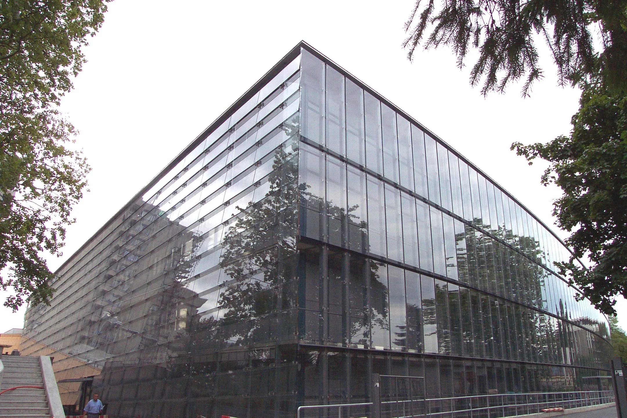
INO
Constructed to keep pace with evolving medical practices, this hospital was the first of many buildings in Bern, Switzerland, to follow the “system separation” principle, with the primary system’s flexible structural grid, the secondary system’s specific programmatic layouts, and the tertiary system’s implementation of hi-tech equipment each designed by an independent team.
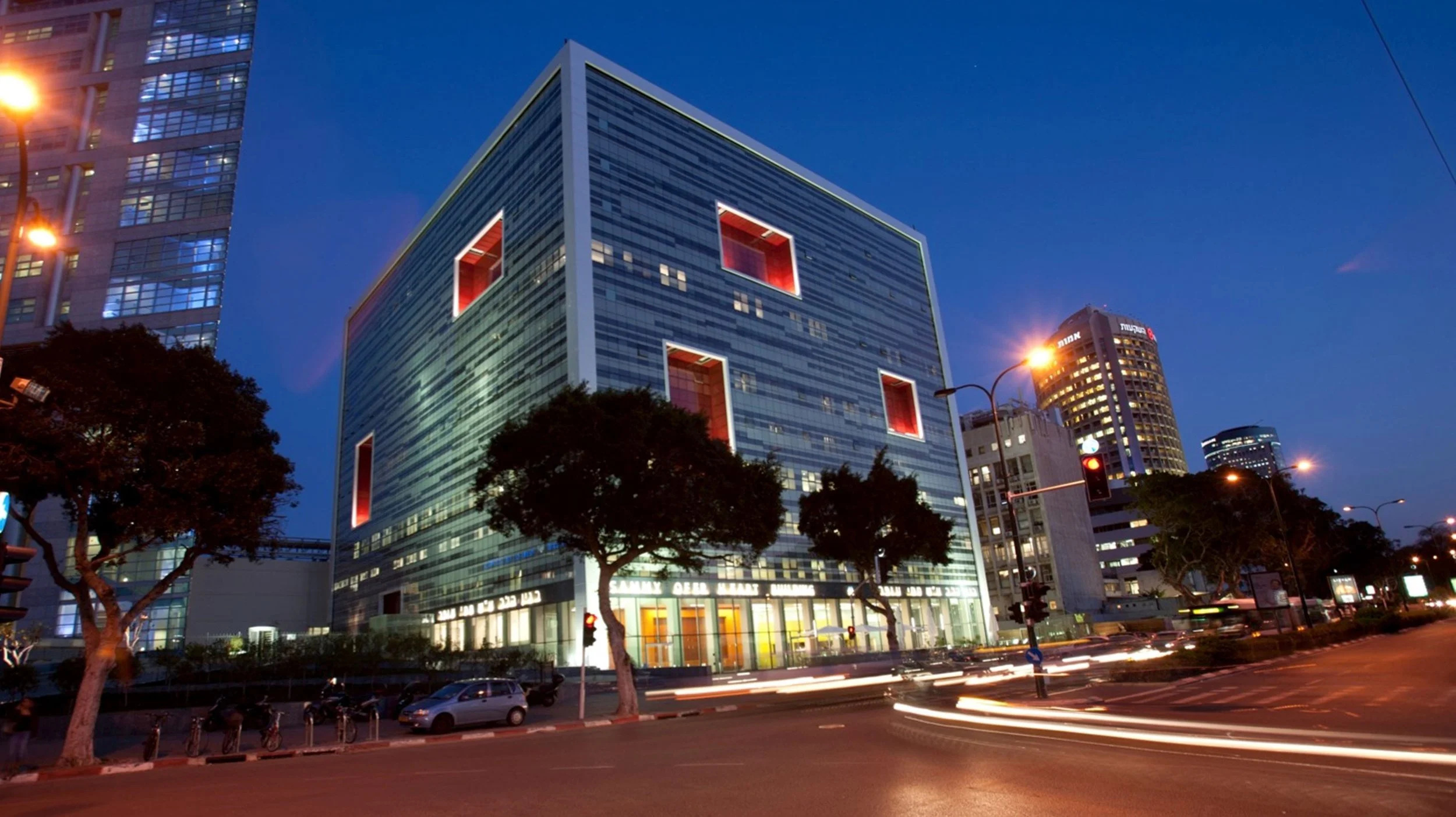
Sammy Ofer Heart Building
An innovative cardiology center in Tel Aviv is designed to accommodate years of uncertainty and programmatic changes with consistent utility pathways that easily accommodate floor-layout modifications and a base-building structure that lends itself to building additional floors.
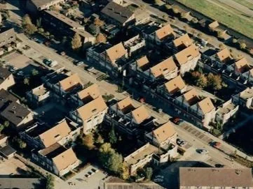
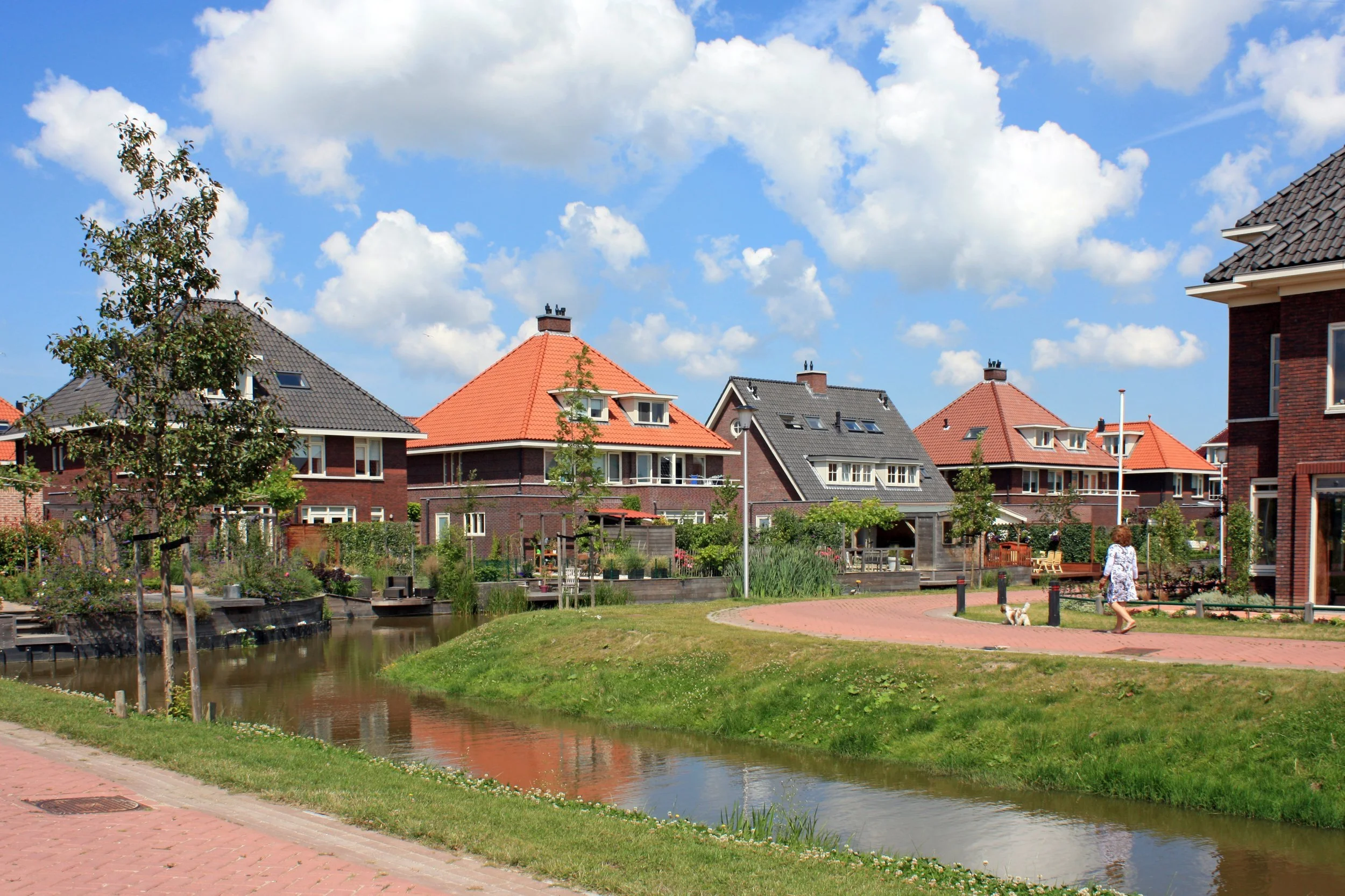
Westpolder Bolwerk
A phased residential development near Rotterdam uses shared urban and spatial themes to coordinate multiple architects, housing types, and price points, creating a seamlessly harmonized yet diverse neighborhood.
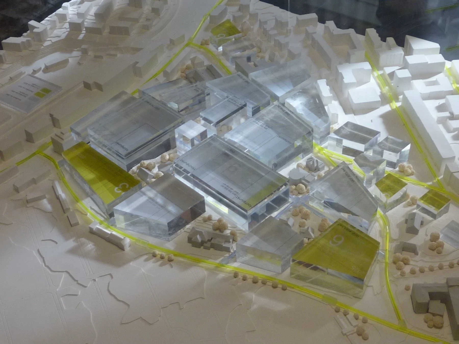
Inselspital Medical Campus
A 50-year masterplan for Inselspital in Bern enables the phased transformation of Switzerland’s largest hospital site by balancing short-term upgrades with long-term flexibility rooted in rule-based design.
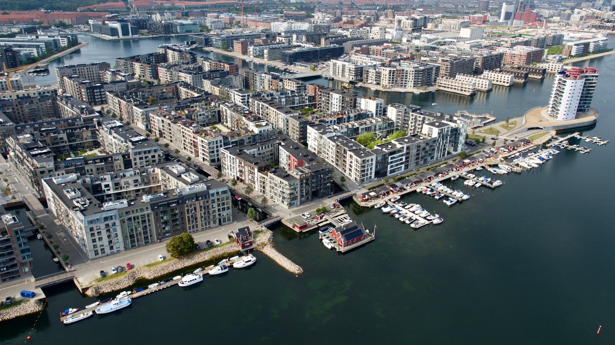
Sydhavnen (Sluseholmen)
Inspired by historic urban patterns, a master architect's plan transforms a Copenhagen harbor area into a dense residential neighborhood where distinct architects design each block’s structure and additional architects design facades according to shared architectural themes.
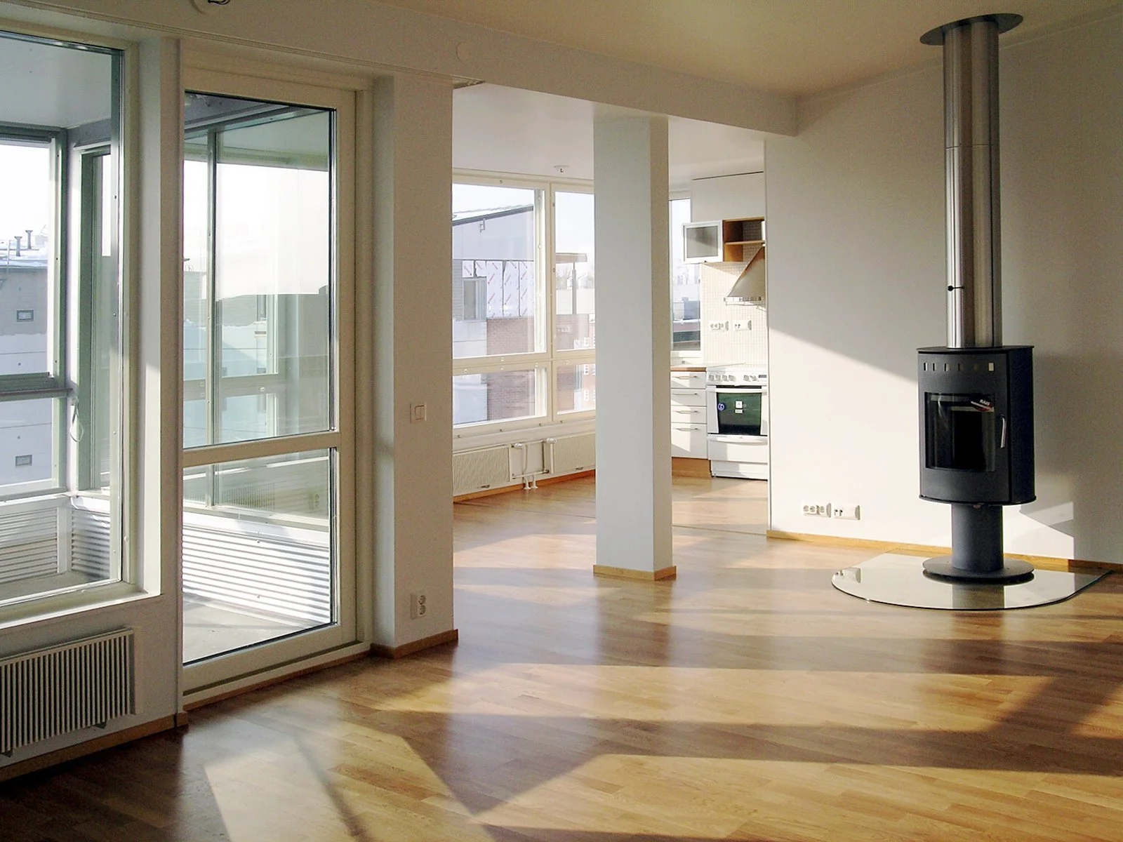
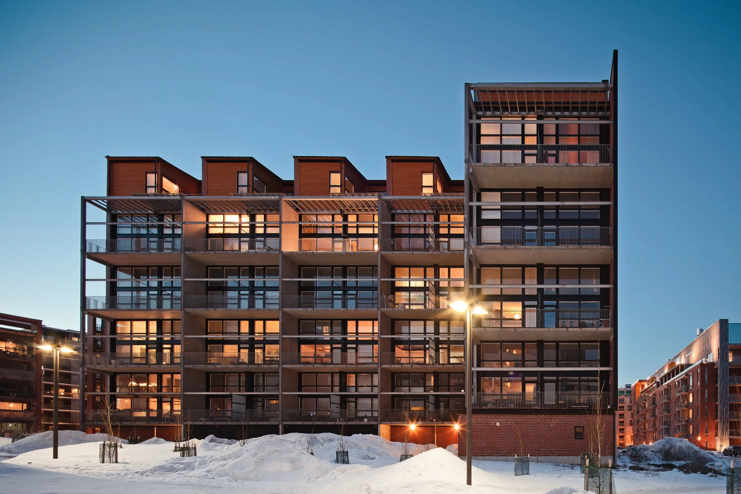
Arabianranta
An award-winning mid-rise housing project in Helsinki utilizes pioneering data management software as it entrusts residents with meaningful agency over their dwellings’ layouts and finishes.
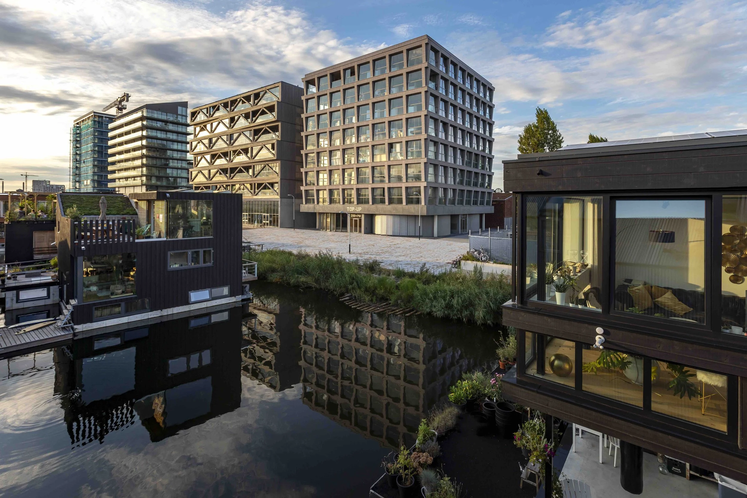
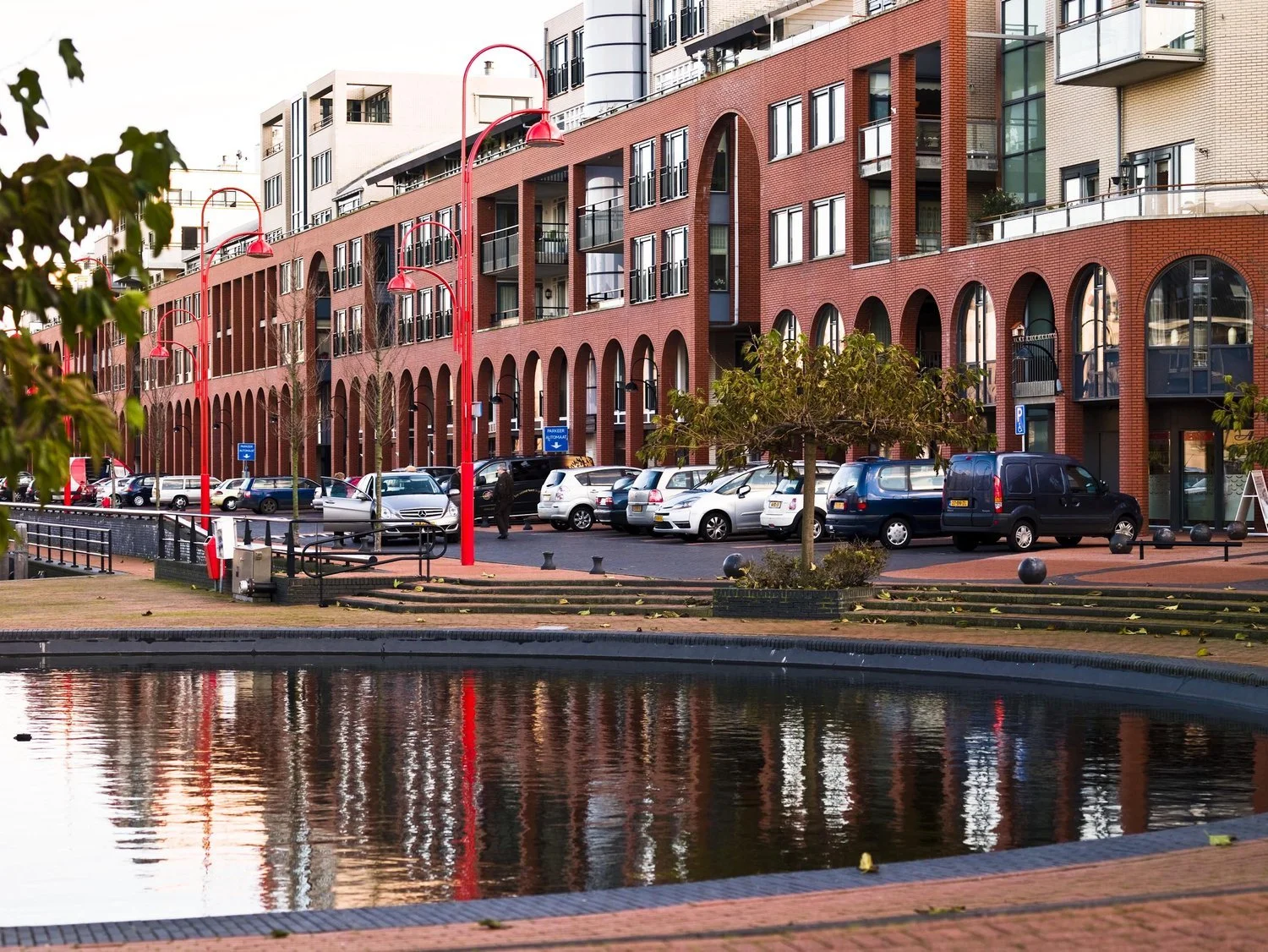
Princehaven
A masterplan for a mixed-use harbor-front redevelopment in Katwijk, Netherlands, provides a thematic “urban design structure” under which five distinct architecture firms co-create an architecturally varied yet coherent neighborhood with shared circulation patterns and parking.
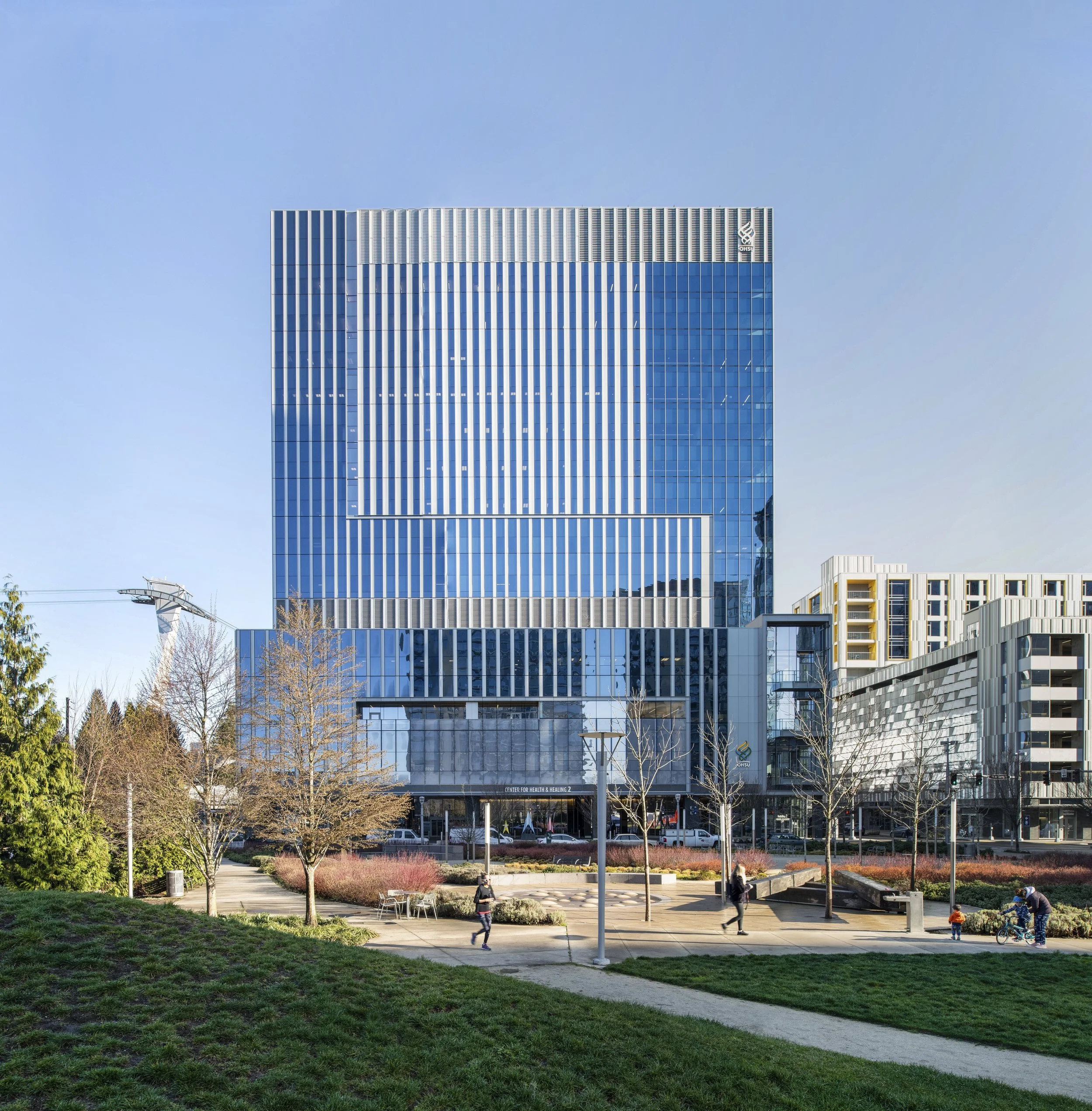
OHSU Health & Healing Center
A 15-story ambulatory health center constructed on a tight footprint demonstrates Open Building flexibility by separating “hard” structural/service zones from “soft” spaces to accommodate diverse user-driven programming within a resilient, high-performance facility.
Molenvliet
Molenvliet is one of the world’s first full-scale implementations of Open Building—a rental housing complex composed of 120+ units structured in a traditionally Dutch vernacular, each filled-in with a uniquely tailored layout and facade
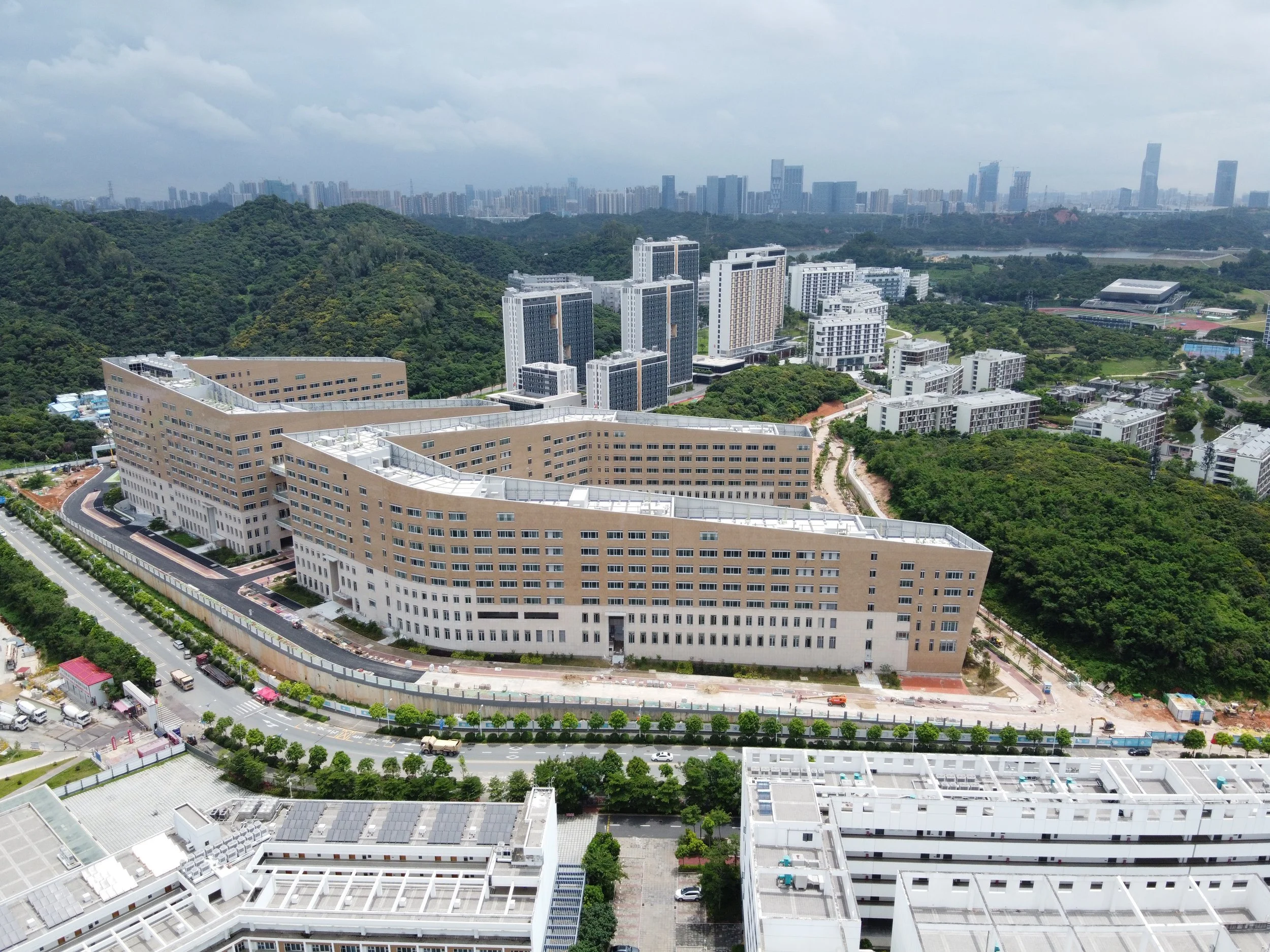
SUSTC School of Engineering
A large engineering complex housing nine academic departments uses Open Building to prepare for a century of shifting programs, labs, and staffing within a consistent architectural infrastructure.
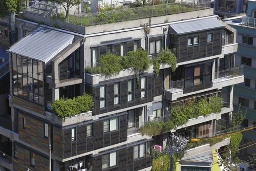
NEXT21
A pioneering housing project in Osaka experiments with new energy systems, interior fit-outs, a facade system “kit-of-parts,” and urban greenery while using the Open Building principle of separating design tasks so that each residence can be continually designed, reconfigured, combined, or replaced independent of the others.
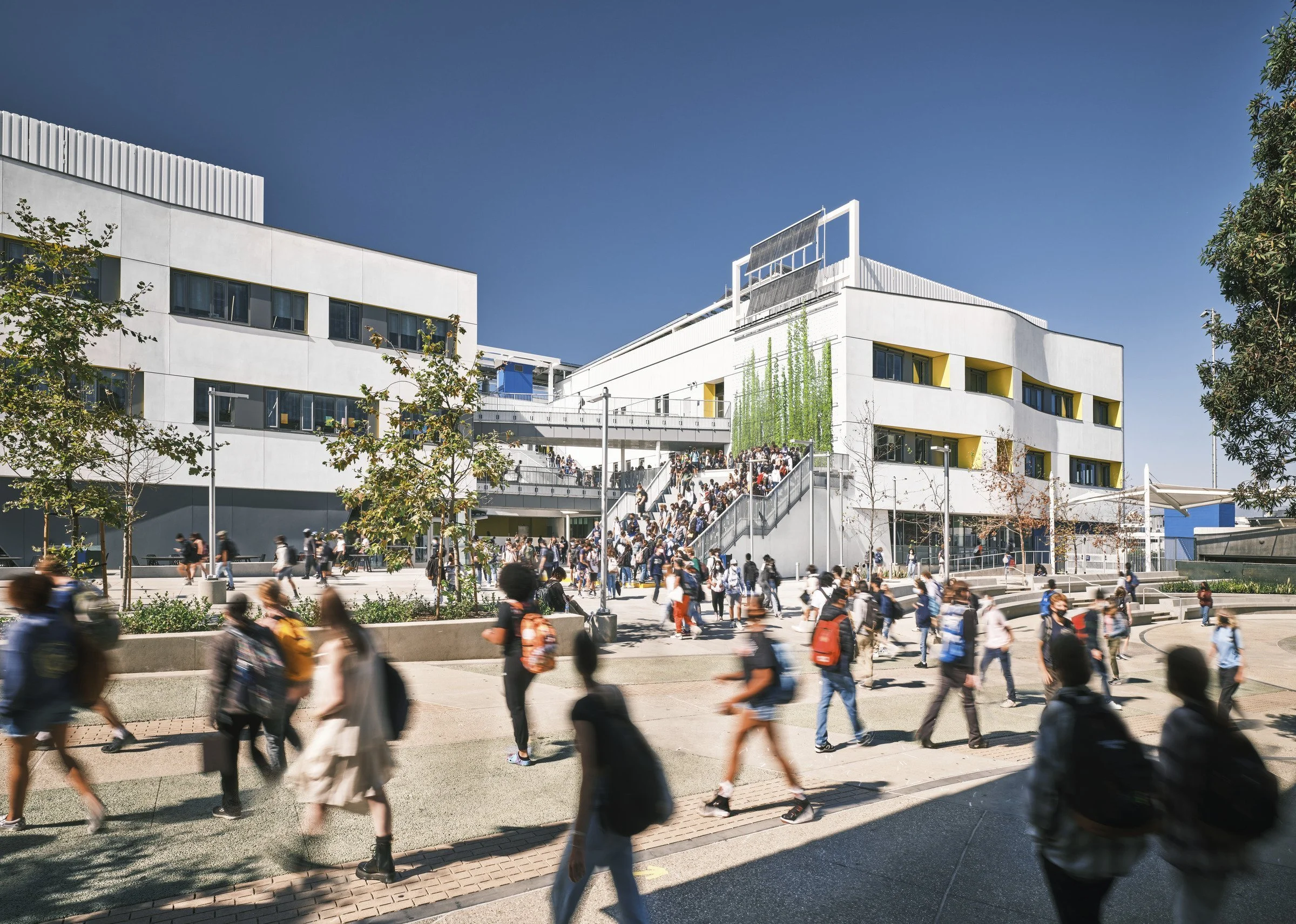
Discovery Building
An Open Building design revitalizes a Southern California high school’s century-old campus with a structure equipped to adapt to the next 100 years of educational innovation.